
An Oil Offloading Pump transfers crude oil or refined product from a tanker, barge, storage vessel, or offshore facility. It is the working heart of a controlled unloading operation. The pump must move thick, sometimes warm fluid through long pipelines while maintaining stable pressure. Small errors can become expensive delays.
Rotating-equipment authority Heinz P. Bloch offers a practical principle: “A pump’s reliability depends on the details surrounding its operation.” That lesson fits oil offloading closely. The pump alone does not complete the transfer. Suction piping, strainers, valves, hoses, meters, seals, and control systems must work together. A blocked strainer can reduce flow. Poor alignment can increase vibration. An unnoticed leak can create a serious operational and environmental concern.
The basic process is straightforward. The pump creates lower pressure at its suction side. Atmospheric or vessel pressure then pushes oil toward the impeller or rotor. Internal energy raises the fluid pressure. The discharge line carries oil into a tank or pipeline. It sounds simple. Real systems are less tidy.
This guide explains what an Oil Offloading Pump is, how it works, and why pump selection matters. It also examines centrifugal and positive-displacement designs, common components, operating limits, and routine inspection points. Field experience often challenges textbook assumptions. Oil temperature changes. Cargo viscosity shifts. Marine movement adds uncertainty. Even a well-designed system can perform poorly when operators overlook these details. Good offloading practice requires technical knowledge, careful observation, and a willingness to question normal-looking readings.
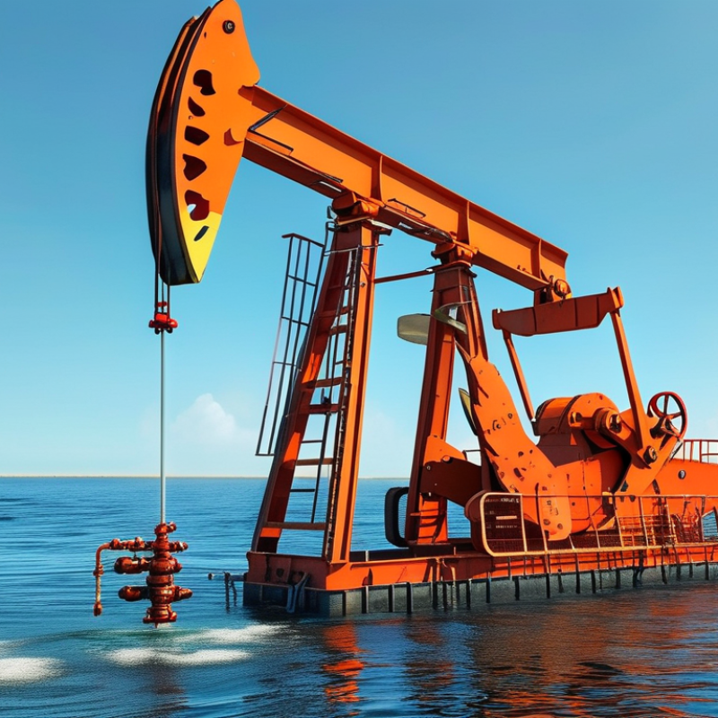
An oil offloading pump is a mechanical device that transfers oil from a storage vessel to a pipeline, tanker, truck, or processing unit. It creates the pressure needed to move oil through connected hoses and valves. Without this pump, gravity alone may not provide a steady flow.
Most offloading systems use a centrifugal or positive displacement pump. A centrifugal pump suits larger volumes and relatively stable flow. A positive displacement pump handles thicker oil and delivers controlled quantities. The selected type depends on viscosity, temperature, transfer distance, and required flow rate. Operators also check seal condition, suction pressure, and filter cleanliness before starting.
During operation, the suction line draws oil from the vessel. The pump then raises its pressure and pushes the liquid through the discharge line. Valves regulate direction and flow. Gauges reveal unusual pressure changes. A sudden drop may suggest air entering the suction line, while high pressure can indicate a blocked filter or closed valve.
Small details matter. Warm oil may flow more easily, but excessive heat can damage seals or create safety concerns. In practice, the process is rarely perfect. Viscosity can change during transfer, and readings may not match calculations exactly. Experienced operators monitor the pump instead of trusting one instrument. They stop the system when vibration, leakage, or abnormal noise appears. Safety procedures, grounding, spill control, and routine maintenance remain essential for reliable oil offloading.
An oil offloading pump transfers crude oil from a storage vessel to a shuttle tanker. On an FPSO, it operates through cargo pipelines, valves, and loading arms. The IEA’s Oil 2024 report projects global oil demand will reach 105.4 million barrels per day by 2030. Reliable transfer equipment will remain important, despite changing energy systems.
The pump casing guides liquid through the machine. Inside, an impeller adds velocity to the oil. A centrifugal design suits high-volume transfer, while positive-displacement pumps support steadier flow at higher resistance. The driver supplies rotational power. It may use an electric motor or hydraulic turbine. Shaft seals reduce leakage around the rotating shaft. They need careful inspection. A suction strainer protects the impeller from debris, although excessive restriction can cause cavitation.
The discharge manifold directs oil toward the loading hose or marine arm. Isolation valves control maintenance and emergency shutdowns. Pressure, temperature, vibration, and flow instruments help operators detect abnormal conditions early. API Standard 610 provides widely used requirements for centrifugal pump design and testing. In practice, alignment matters as much as pump size. Poor alignment can increase vibration, seal wear, and energy use. The U.S. Energy Information Administration reports that offshore production remains a significant part of global petroleum supply, making equipment reliability a practical concern. A small mistake in valve sequencing can still interrupt an otherwise capable system.
An oil offloading pump transfers oil from a vessel, tanker, or storage container into a receiving tank. The pump creates enough pressure to move oil through hoses, valves, and pipelines. During offloading, operators monitor flow rate, pressure, temperature, and tank capacity. These readings help prevent spills, overfilling, and equipment stress.
The process begins with a careful inspection of connections, valves, hoses, and emergency shutoff systems. Operators confirm that the receiving tank has enough space. Pressure matters. A flexible hose may look secure but still leak under load. Once the transfer path is ready, the pump starts at a low speed. The crew then increases the flow gradually while checking gauges and nearby joints.
Inside the pump, rotating components push oil through the discharge line. Heavier or colder oil may move more slowly because its viscosity increases. Flow meters record the transferred volume, while level sensors track the receiving tank. Operators compare both readings throughout the operation. If readings disagree, they reduce the flow and investigate rather than guessing.
At the end, the crew closes valves in a controlled sequence and drains trapped oil into approved collection equipment. Vapor control and grounding also reduce operational hazards. In real operations, small details matter. A partially closed valve can cause heat, vibration, or pressure spikes. It is not glamorous. Careful observation often prevents the most expensive mistakes.
An oil offloading pump transfers oil from a tanker, rail car, or storage vessel into a receiving tank. It must handle changing viscosity, suction conditions, and transfer distances. In practical installations, pump selection depends on flow rate, pressure, temperature, and oil thickness. A small mismatch can cause slow loading or excessive wear. The pump should also include suitable seals, strainers, pressure gauges, and emergency shutoff controls.
Centrifugal pumps suit low to medium-viscosity oils and steady, high-volume transfer. They provide smooth flow but may struggle with thick oil or poor suction conditions. Positive displacement pumps, including gear and screw types, handle heavier oils more effectively. They deliver measured flow at higher pressures, so a relief valve is essential. Diaphragm pumps can manage intermittent service and contaminated fluids, although their flow may pulsate. Each type has trade-offs. No pump is perfect. Engineers should review actual operating data instead of relying only on catalog ratings.
Tips: Check oil viscosity at the real operating temperature. Confirm the pump’s suction lift and available pressure. Keep the suction line short and generously sized. Watch for air leaks, because small leaks can interrupt flow. Inspect seals and filters regularly. It is also wise to record transfer time, pressure, and motor load. These simple records often reveal problems before failure. Safety procedures must match the site, equipment, and applicable regulations.
| Oil Pump Type | How It Works | Typical Oil Transfer Applications | Suitable Oil Characteristics | Typical Flow Range* | Main Advantages | Common Limitations |
|---|---|---|---|---|---|---|
| Centrifugal Pump | A rotating impeller increases the liquid's velocity, and the casing converts part of that velocity into pressure for continuous flow. | High-volume offloading from tank trucks, storage tanks, pipelines, and marine vessels. | Low- to medium-viscosity oils and petroleum liquids with relatively low solids content. | Approximately 20–5,000 m³/h | High capacity, smooth flow, compact design, and generally lower purchase cost. | Performance decreases with very viscous oil; usually requires adequate suction conditions and may need priming. |
| Positive Displacement Gear Pump | Meshing gears trap oil between the gear teeth and casing, then carry a nearly fixed volume from the suction side to the discharge side. | Transfer of lubricating oil, fuel oil, crude oil, and other viscous products between tanks and process equipment. | Medium- to high-viscosity oils; clean liquids with limited abrasive particles. | Approximately 0.1–500 m³/h | Good self-priming capability, steady flow, and effective handling of viscous liquids. | Relief protection is required because discharge pressure can rise rapidly if the outlet is blocked; abrasive solids can accelerate wear. |
| Screw Pump | One or more rotating screws create sealed cavities that move oil axially through the pump with low pulsation. | Crude oil transfer, fuel oil loading, pipeline boosting, and applications requiring continuous low-pulsation flow. | Low- to very high-viscosity oils, including some oils containing small amounts of entrained gas. | Approximately 1–2,000 m³/h | Quiet operation, low pulsation, good suction performance, and efficient handling of viscous liquids. | More sensitive to dry running and abrasive contamination; internal clearances and lubrication must be properly maintained. |
| Sliding Vane Pump | Spring-loaded vanes slide in and out of a rotor, forming changing-volume chambers that draw in and discharge oil. | Fuel dispensing, truck loading and unloading, metered transfer, and mobile oil-handling systems. | Low- to medium-viscosity fuels and oils with good lubricity and low solids content. | Approximately 1–250 m³/h | Strong self-priming ability, reversible operation on many designs, and good vapor-handling capability. | Vanes and the internal surface can wear when exposed to abrasive particles or inadequate lubrication. |
| Lobe Pump | Counter-rotating lobes carry oil in cavities from the inlet to the outlet without direct contact between the lobes. | Gentle transfer of specialty oils, additives, blended oils, and liquids requiring low shear. | Low- to high-viscosity oils; some designs can handle limited soft solids. | Approximately 0.5–300 m³/h | Low shear, easy cleaning on hygienic designs, and relatively gentle product handling. | Often has lower pressure capability than some other positive-displacement pumps and may lose efficiency if clearances increase. |
| Diaphragm Pump | A reciprocating diaphragm changes the chamber volume and uses check valves to draw in and discharge oil. | Small-scale transfer, difficult suction conditions, intermittent offloading, and locations without electric power when air-operated. | Low- to medium-viscosity oils; the wetted materials must be compatible with the oil. | Approximately 0.01–100 m³/h | Can run dry for limited periods, offers good suction lift, and is available in air-operated configurations. | Pulsating flow, lower efficiency for continuous high-volume transfer, and diaphragm wear over time. |
| Reciprocating Piston or Plunger Pump | A piston or plunger moves back and forth, using suction and discharge valves to transfer a measured volume of oil per stroke. | High-pressure injection, accurate dosing, hydraulic applications, and specialized transfer duties. | Clean, low- to medium-viscosity oils; suitable fluid properties depend on the seal and valve design. | Approximately 0.01–200 m³/h | High discharge pressure, accurate displacement, and strong performance in metering applications. | Pulsating output, more moving parts, and greater maintenance requirements than many rotary pumps. |
| Submersible Oil Transfer Pump | The pump is installed inside or near the bottom of a tank, so the liquid surrounds the pump inlet and reduces suction-lift requirements. | Tank drainage, temporary offloading, confined installations, and applications where priming is difficult. | Oil type and viscosity must match the motor, seals, cooling method, and pump construction. | Approximately 5–1,000 m³/h | Reduced suction piping, low priming risk, and effective use of available tank head. | Maintenance may require tank access or pump removal; electrical and hazardous-area requirements must be addressed. |
What Is an Oil Offloading Pump and How Does It Work?
An oil offloading pump transfers oil from a tanker, truck, or vessel into a storage tank. Its impeller creates flow by reducing pressure at the suction side. Discharge pressure then pushes oil through the transfer hose. Flow meters and pressure gauges help operators control the movement. The pump must match the oil’s viscosity, temperature, and transfer distance.
Safety starts before the motor runs. Operators should inspect hoses, couplings, seals, valves, and grounding connections. A loose coupling can release oil within seconds. Keep ignition sources away from the transfer area. Confirm that emergency stops work and that spill equipment is accessible. Never open a valve suddenly; pressure can rise sharply. Clear communication matters during every connection and disconnection.
Maintenance requires more than changing oil and checking bolts. Technicians should monitor vibration, unusual noise, seal leakage, and rising motor temperature. A pump can sound normal while cavitating. Low suction levels, blocked strainers, or restricted hoses may cause this damage. Clean strainers regularly, but do not ignore repeated blockage. It may indicate tank contamination. Accurate maintenance records reveal patterns that memory misses. Even a careful checklist has limits. Weather, operator fatigue, and poor lighting can still create risk. Stop the transfer when readings become uncertain.
An oil offloading pump transfers liquid oil from a tanker, railcar, vessel, or storage container into a receiving system. The operating profile below shows representative flow-rate changes during a typical transfer cycle. Actual values depend on pump size, oil viscosity, pipeline resistance, and site procedures.
Operators normally start at a low flow rate to confirm valve alignment, hose integrity, grounding, and leak-free connections. Flow is then increased gradually during steady transfer and reduced before shutdown to limit pressure surges. Regular checks of vibration, seal condition, bearing temperature, suction pressure, discharge pressure, and emergency-stop systems support safe and reliable operation.